


 185 / 221

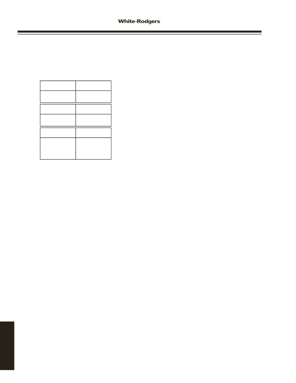
OPTION SWITCHES
The option switches on the 50A65-843 control are used to
determine the length of the cool delay-to-fan-off, heat delay-
to-fan-on and heat delay-to-fan-off periods. The following
table shows the time periods that will result from the various
switch positions.
HEAT MODE
In a typical system, a call for heat is initiated by closing the
thermostat contacts. This starts the 50A65 control’s heating
sequence. The inducer blower and optional humidifier are
energized and the 768A silicon nitride ignitor is powered
within one second.
This control has an adaptive algorithm that reduces the ignitor
temperature to slightly greater than the minimum temperature
required to ignite gas in each particular application. The con-
trol measures the line voltage and determines an initial ignitor
temperature setting based on the measurement. After each
successful ignition, the control lowers the ignitor temperature
slightly for the next ignition attempt. The control continues to
lower the ignitor temperature until ignition does not occur, and
the control goes into retry mode. For the second attempt to
ignite gas within the same call for heat, the control increases
the ignitor temperature to the value it was on the third previ-
ous successful ignition. After ignition is successful, the control
sets the ignition temperature at this value for the next 255
calls for heat, after which the control repeats the adaptive
algorithm. The control is constantly making adjustments to
the ignitor temperature to compensate for changes in the line
voltage.
The 80 VAC Silicon Nitride ignitor manufactured by
White-Rodgers must be used.
These ignitors are specially
designed to operate with the 50A65’s adaptive ignition routine
to ensure the most efficient ignitor temperature.
COOL MODE
In a typical system, a call for cool is initiated by closing the
thermostat contacts. This energizes the 50A65 control and
the compressor. The cool delay-to-fan-on period begins. After
the delay period ends, the optional electronic air cleaner is
energized, and the circulator fan is energized at cool speed.
After the thermostat is satisfied, the compressor is de-
energized and the cool mode delay-to-fan-off period begins.
After the delay-to-fan-off period ends, the circulator fan and
electronic air cleaner (optional) are de-energized.
MANUAL FAN ON MODE
If the thermostat fan switch is moved to the ON position, the
circulator fan (cool speed) and optional electronic air cleaner
are energized. When the fan switch is returned to the AUTO
position, the circulator fan and electronic air cleaner (optional)
are de-energized.
SYSTEM LOCKOUT FEATURES
When system lockout occurs, the gas valve is de-energized,
the circulator blower is energized at heat speed, and, if flame
is sensed, the inducer blower is energized. The diagnostic
indicator light will flash or glow continuously to indicate
system status. (
System lockout will never override the
precautionary features
.)
To reset the control after system lockout,
do one of the
following:
1. Interrupt the call for heat or cool at the thermostat for at
least one second but less than 20 seconds (if flame is
sensed with the gas valve de-energized, interrupting the
call for heat at the thermostat will
not
reset the control).
2. Interrupt the 24 VAC power at the control for at least one
second. You may also need to reset the flame rollout
sensor switch.
3. After one hour in lockout, the control will automatically
reset itself.
DIAGNOSTIC FEATURES
The 50A65-843 control continuously monitors its own
operation and the operation of the system. If a failure occurs,
the LED will indicate a failure code as shown below.
If the
failure is internal to the control, the light will stay on
continuously. In this case, the entire control should be
replaced, as the control is not field-repairable
.
If the sensed failure is in the system (external to the control),
the LED will flash in the following flash-pause sequences to
indicate failure status (each flash will last approximately 0.25
seconds, and each pause will last approximately 2 seconds).
1 flash, then pause
System lockout
2 flashes, then pause Pressure switch stuck closed
3 flashes, then pause Pressure switch stuck open
4 flashes, then pause Open limit switch
5 flashes, then pause Open rollout switch
6 flashes, then pause 115 Volt AC power reversed /
Improper ground
7 flashes, then pause Low flame sense signal
8 flashes, then pause Check ignitor
Continuous flashing
Flame has been sensed when
(no pause)
no flame should be present (no
call for heat)
The LED will also flash once at power-up.
Trane application
- Jumper wire 151-2906 (provided with
control) must be installed on the furnace from R01 to R02 of
the 12-pin connector.
HEAT delay-
to-fan-off:
Set switch
#3 #4
60 sec.
90 sec.
120 sec.
180 sec.*
On On
Off On
On Off
Off Off
COOL delay-
to-fan-off:
Set switch
#1
45 sec.*
90 sec.
On
Off
HEAT delay-
to-fan-on:
Set switch
#2
30 sec.*
45 sec.
On
Off
OPTION SWITCH POSITIONS
* Factory setting
WIRING AND
CONFIGURATION
50A65-843
www.white-rodgers.com186
TECHNICAL HELP