


 184 / 221

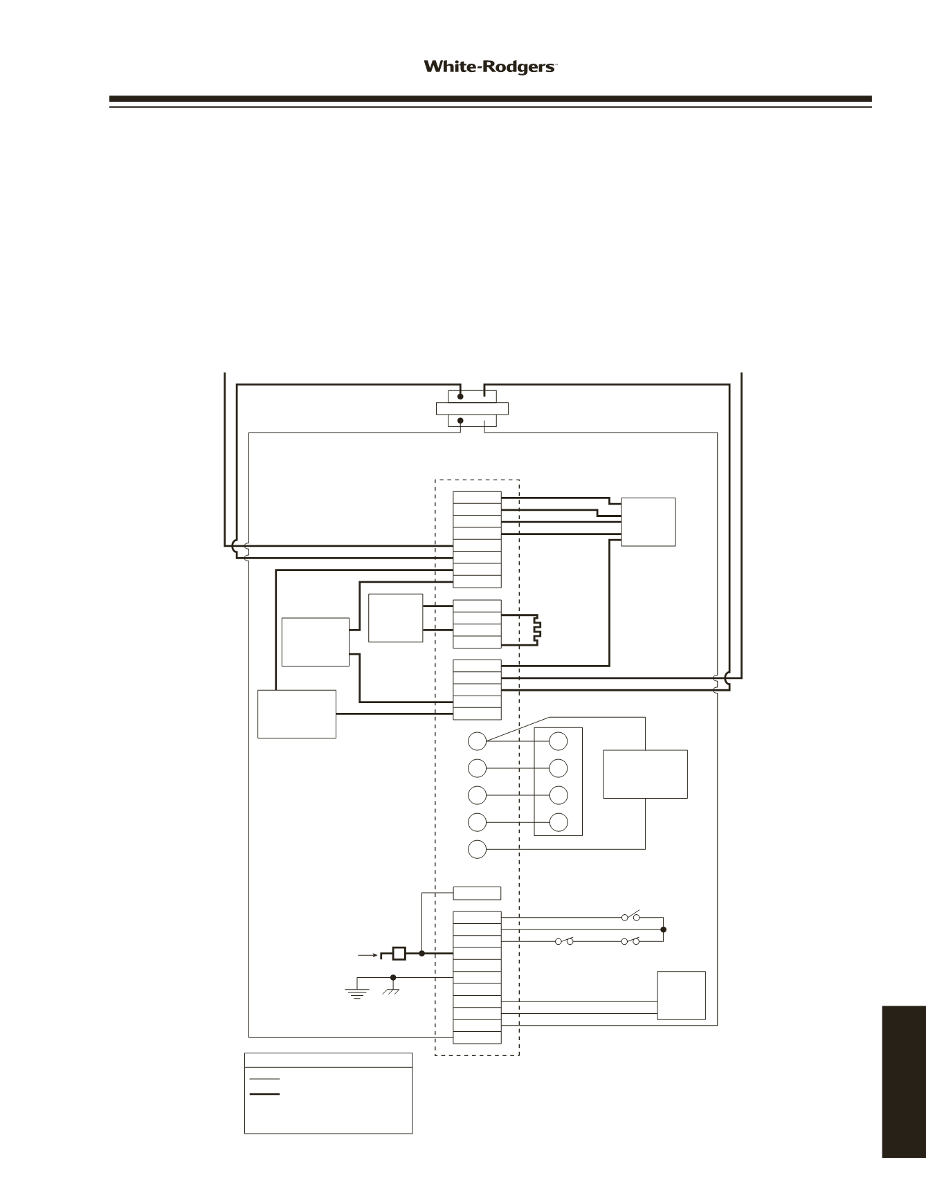
50A65-843
WIRING AND
CONFIGURATION
TH
TR
MV
MV
GND
FP
HLO
HLI
PS
C
R
G
W
Y
EAC N
E33
HUM N
XFMR N
LINE N
CIR N
IGN N
IND N
IGN
IND
HUM
EAC
XFMR
LINE
PARK
PARK
HEAT
COOL
IGNITOR
Y
W
G
R
THERMOSTAT
GAS
VALVE
HIGH LIMIT
(N. C.)
AUX. HIGH
LIMIT (N. C.)
PRESSURE SWITCH (N. O.)
FLAME
SENSOR
PROBE
COMPRESSOR
CONTACTOR
ELECTRONIC
AIR CLEANER
HUMIDIFIER
INDUCER
CIRCU-
LATOR
BLOWER
50A65-843
24 VAC
120 VAC
24 VAC CLASS II
TRANSFORMER
HOT
(LINE)
NEUTRAL
(LINE)
TH
TR
Low Voltage (24 VAC)
Line Voltage (120 VAC)
LEGEND
N. C. = Normally closed switch
N. O. = Normally open switch
TYPICAL SYSTEM WIRING DIAGRAM
The 50A65-843 is an automatic gas interrupted ignition
control that employs a microprocessor to continually monitor,
analyze, and control the proper operation of the gas burner,
inducer, and fan.
Signals interpreted during continual surveillance of the ther-
mostat and flame sensing element initiate automatic ignition
of the burner, sensing of the flame, and system shut-off dur-
ing normal operation.
These controls incorporate system fault analysis for quick gas
flow shut-off, coupled with automatic ignition retry upon sens-
ing a fault correction.
Flame Current Requirements:
Minimum current to insure flame detection.............1 µa DC
➀
Maximum current for non-detection.....................0.1 µa DC
➀
Maximum allowable leakage resistance............. 100 M ohms
Flame establishing time......................0.8 seconds maximum
Flame failure response time................2.0 seconds maximum
➀
Measured with a DC microammeter in the flame probe lead
50A65-843
www.white-rodgers.com185
TECHNICAL HELP