


 190 / 221

OPERATION
50M56U-843
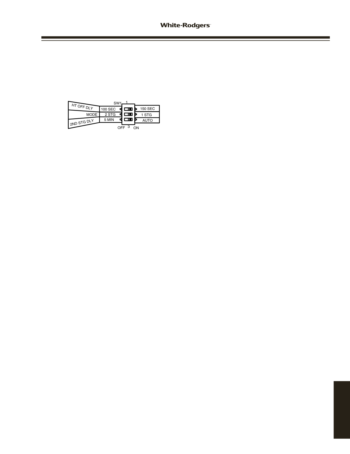
OPTION SWITCHES
The option switches on the 50M56U-843 control are used to
determine the length of the heat delay-to-fan-off period, the
mode of operation, and the 2nd stage delay period. The following
illustration shows the options and the selections of the switch
positions. The switches are shown in the factory default positions.
HEAT MODE
When heat is required, the thermostat will send a call for heat to
the control. This starts the controls heating sequence. The ignitor
and humidifier (optional) are powered. The ignitor is powered after
the pre-purge period.
Upon initial application of power, the warm-up time is 17 seconds.
The ignitor on-time will then be increased depending on whether or
not flame is achieved.The warm-up time is limited to a maximum of
19 seconds. During the first 64 warm-up periods following power-
up, the warm-up time may not be less than 17 seconds.
In the event of a retry, the warm-up time will be increased by one
second and locked in at that duration. Once the warm-up time is
locked, it remains fixed until another call for heat results in a retry,
in which case the warm-up time is again increased by one second
and remains locked.
In the event of two successive retry attempts, the warm-up time will
be unlocked and set to 19 seconds. If flame is then achieved, the
warm-up time will begin adapting again with the next call for heat.
If, however, this third attempt fails to achieve flame, the control will
go into system lockout.
After the ignitor warm-up period, MV LO (first stage) and MV HI
(second stage) are both energized to the gas valve. Flame must
be detected within 4 seconds. If flame is detected, the 30-second
HEAT delay-to-fan-on period begins. The circulator and electronic
air cleaner (optional) will also energize at this time.
1 Stage operation
– If the Option Switch MODE (SW1-2) is set to
the 1 STG position, both MV LO and MV HI will remain energized.
2 Stage operation (Goodman 50M56-289 Application only)
– If
the Option Switch MODE is set to 2 STG, MV HI will de-energize
after 5 seconds, leaving MV LO energized. If the MODE is in the
2 STG position, 2nd STG DLY (SW1-3) will determine the second
stage- on delay as follows:
5 MIN
– On call for heat, the 5 minute 2nd stage recognition
timer begins. After the 5-minute delay, the second stage heat
(MV HI) is energized.
AUTO
– On call for heat, the automatic second stage will
determine the optimum timing between stages for comfort. Auto
will adapt the delay to energize MV HI from instantly to up to 12
minutes.
When the thermostat is satisfied, the gas valve is de-energized.
After proof of flame loss, the heat delay-to-fan-off period begins
and the inducer blower remains energized to purge the system for
25 seconds. When the purge is complete, the inducer blower is de-
energized. After the delay-to-fan-off period ends, the circulator fan
and electronic air cleaner are de-energized.
If flame is not detected, both valves are de-energized, the ignitor
*
*
*MODE and 2ND STG DLY for Goodman 50M56-289 only
is turned off, and the 50M56U-843 control goes into the “retry”
sequence. The “retry” sequence provides a 60-second wait
following an unsuccessful ignition attempt (flame not detected).
After this wait, the ignition sequence is restarted with an additional
1 second of ignitor warm-up time.
If flame is established for more than 10 seconds after ignition,
the 50M56U-843 controller will clear the ignition attempt (or retry)
counter. If flame is lost after 10 seconds, it will restart the ignition
sequence.
During burner operation, a momentary loss of power of 50
milliseconds or longer will de-energize the main gas valve. When
power is restored, the gas valve will remain de-energized and a
restart of the ignition sequence will begin immediately.
A momentary loss of gas supply, flame blowout, or a shorted or
open condition in the flame probe circuit will be sensed within 2.0
seconds. The gas valve will de-energize and the control will restart
the ignition sequence. Recycles will begin and the burner will
operate normally if the gas supply returns, or the fault condition
is corrected.
If the control has gone into system lockout, it may be possible to
reset the control by a momentary power interruption of one second
or longer. Refer to
SYSTEM LOCKOUT FEATURES
.
COOL MODE
In a typical system, a call for cool is initiated by closing the
thermostat contacts. This energizes the 50M56U-843 control and
the compressor. The cool delay-to-fan-on period begins. After the
delay period ends, the optional electronic air cleaner is energized,
and the circulator fan is energized at cool speed. After the
thermostat is satisfied, the compressor is de-energized and the
cool mode delay-to-fan-off period begins. After the delay-to-fan-off
period ends, the circulator fan and electronic air cleaner (optional)
are de-energized.
MANUAL FAN ON MODE
If the thermostat fan switch is moved to the ON position, the
circulator fan (low heat speed) and optional electronic air cleaner
are energized. When the fan switch is returned to the AUTO
position, the circulator fan and electronic air cleaner (optional) are
de-energized.
SYSTEM LOCKOUT AND
DIAGNOSTIC FEATURES
SYSTEM LOCKOUT FEATURES
When system lockout occurs, the gas valve is de-energized, the
circulator blower is energized at heat speed, and, if flame is sensed,
the inducer blower is energized. The diagnostic indicator light will
flash or glow continuously to indicate system status.
(System
lockout will never override the precautionary features.)
To reset the control after system lockout,
do one of the
following:
1. Interrupt the call for heat or cool at the thermostat for at least
one second but less than 20 seconds (if flame is sensed with
the gas valve de-energized, interrupting the call for heat at the
thermostat will not reset the control).
2. Interrupt the 24 VAC power at the control for at least one
second. You may also need to reset the flame rollout sensor
switch.
3. After one hour in lockout, the control will automatically reset
itself.
www.white-rodgers.com191
TECHNICAL HELP