


 191 / 221

OPERATION
50M56U-843
DIAGNOSTIC FEATURES
The 50M56U-843 control continuously monitors its own operation
and the operation of the system. If a failure occurs, the LED will
indicate a failure code as shown below.
If the failure is internal to
the control, the light will stay off. In this case, the entire control
should be replaced, as the control is not field-repairable.
If the sensed failure is in the system (external to the control), the
LED will flash in the following flash-pause sequences to indicate
failure status (each flash will last approximately 0.25 seconds, and
each pause will last approximately 2 seconds).
DIAGNOSTIC INDICATOR FLASH CODES
FLASH
1
System Lockout (Retries Exceeded)
2
Pressure Switch Stuck Closed
3
Pressure Switch Stuck Open
4
Open High Temperature Limit Switch
5
Flame Sensed with Gas Valve De-energized
6
Open Rollout Switch
7
Low Flame Sense Signal
8
Ignitor Relay Fault
Rapid Flash
Reverse Polarity
Continuous On
Normal Operation
Off
Control Failure
FAULT RECALL
The last five fault codes stored can be displayed on the diagnostic
LED.When the control is in standby mode (no call for heat or cool),
press the FAULT RECALL switch for approximately two seconds or
until the diagnostic LED turns off. Release the switch and the LED
will remain off for two seconds. Then the fault codes will display
beginning with the most recent fault first with a two second pause
between codes. After the stored fault codes have all displayed, the
LED will remain off for two seconds and then turn on to indicate
return to normal status.While displaying the stored fault codes, the
control will ignore any new call for heat, cool or fan.
FAULT CODE RESET
The stored fault codes can be erased from memory. When the
control is in standby mode (no call for heat or cool), press the FAULT
RECALL switch for five to ten seconds or until the diagnostic LED
begins to rapid flash. When the switch is released, the LED will
turn off for two seconds to indicate the codes are erased. After two
seconds the LED will turn on to indicate return to normal status. If
the switch is held pressed for over ten seconds the rapid flash will
stop and the LED will be on to indicate return to normal status.
Auto Restart
– After one (1) hour of internal or external lockout,
the control will automatically reset itself and go into an auto
restart purge for 60 seconds.
Cool Delay-To-Fan-Off
– The period of time between the loss
of a call for cool and the deactivation of the blower motor at
Cool speed.
Cool Delay-To-Fan-On
–
The period of time after a thermostat
demand for cool before energizing the circulator blower motor
at Cool speed.
Flame Failure Response Time (FFRT)
–
The period of time
between loss of the supervised main burner flame and the
action to shut off the gas supply.
Heat Delay-To-Fan-Off
– The period of time between the loss
of a call for heat and the deactivation of the blower motor at
Heat speed.
Heat Delay-To-Fan-On
– The period of time between proof of
the supervised main burner flame and the activation of the
blower motor at Heat speed.
IgniterWarm-upTime
–
The length of time allowed for the igniter
to heat up prior to the initiation of gas flow.
Ignition Activation Period (IAP)
–
The period of time between
energizing the main gas valve and deactivation of the ignition
means prior to the end of TFI.
Inter-purge
– The period of time intended to allow for the
dissipation of any unburned gas or residual products of
combustion between the failed trial for ignition and the retry
period.
Post-purge Time
– The period of time intended to allow for
the dissipation of any unburned gas or residual products of
combustion at the end of a furnace burner operating cycle.
Post-purge begins at the loss of flame sense.
Pre-purge Time
– The period of time intended to allow for the
dissipation of any unburned gas or residual products of
combustion at the beginning of a furnace operating cycle
prior to initiating ignition.
Recycles
–
The additional attempts within the same thermostat
cycle for ignition after loss of the supervised ignition source
or the supervised main burner flame.
Retries
– The additional attempts within the same thermostat
cycle for ignition when the supervised main burner flame is
not proven within the first trial for ignition period.
Trial for Ignition Period (TFI)
–
The period of time between
initiation of gas flow and the action to shut off the gas flow in
the event of failure to establish proof of the supervised ignition
source or the supervised main burner flame.
DEFINITION OF TERMS
IMPORTANT:
For continuous fan speed operation, one of the un-
used parked motor taps must be connected to the low heat speed
terminal. Failure to do this will result in the blower not energizing in
the constant fan mode operation. Refer to figure 1.
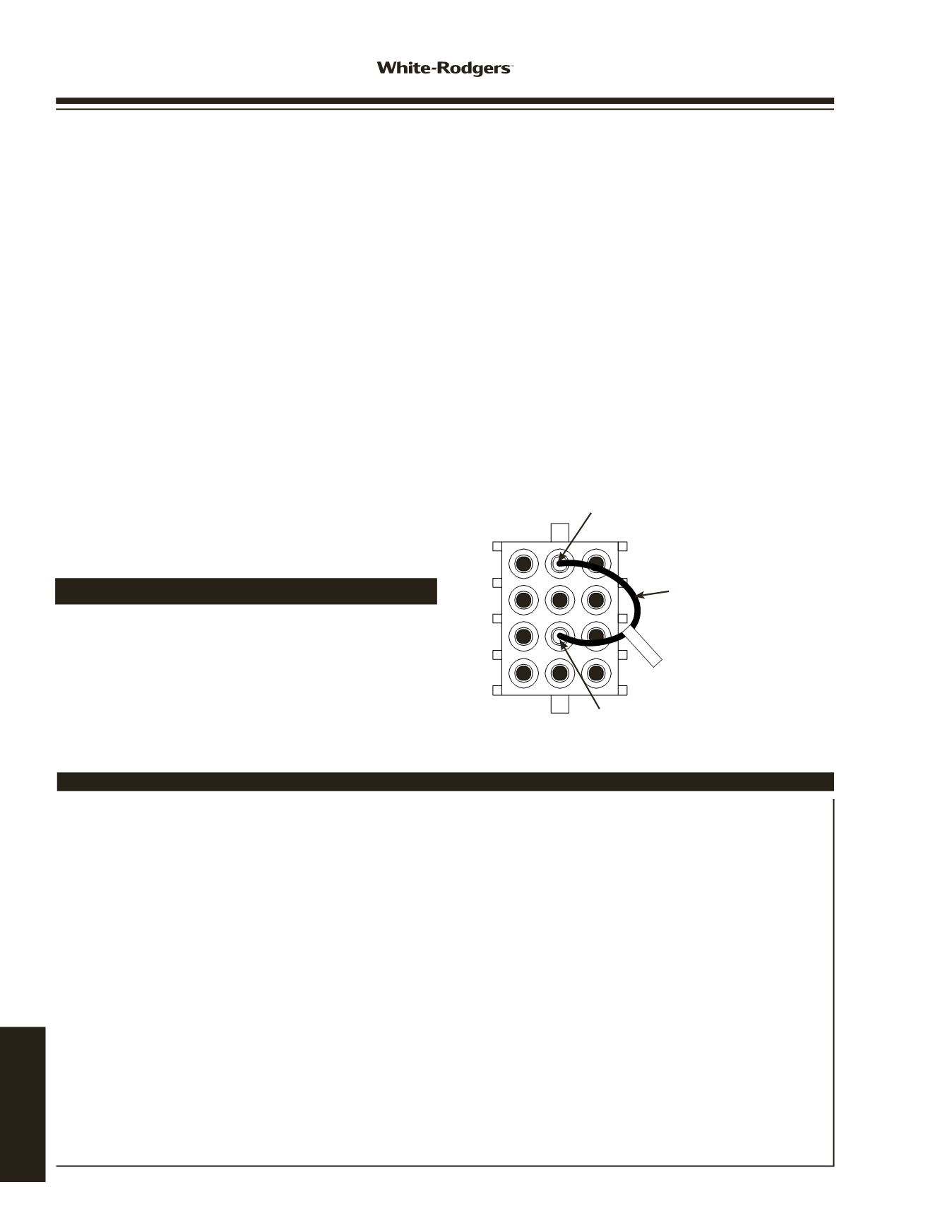
For all Trane and AMERICAN STANDARD applica-
tions only:
Install jumper 0151 290600 (included in this pack-
age) in the furnace 12 pin connector harness, pin 5 and pin 11
positions. Make sure jumper snaps into the connector securely.
Refer to figure 1.
INSTALLER MUST READ FOR PROPER INSTALLATION
290600
J
Pin 11 (R10 In)
Pin 5 (R10 Out)
Jumper 0151-290600
(for Trane and American
Standard Applications only)
www.white-rodgers.com192
TECHNICAL HELP