


 192 / 221

7/16"
15/16"
1 3/8"
15/32"
9/16"
2 1/2"
2 11/16"
2 13/32"
9/16"
3 11/32"
4 1/8"
1 9/16"
1 "
3 7/16"
BREAK OFF TABS
1/2" STC CONDUIT HUB
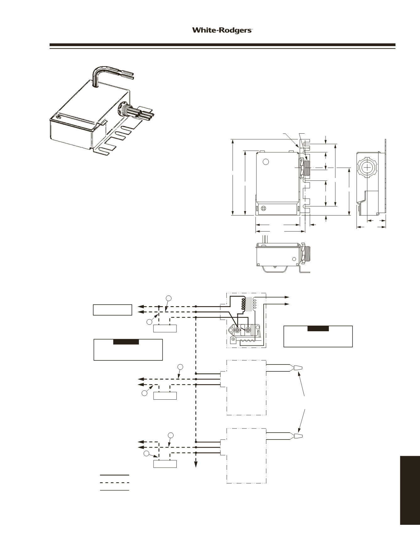
Dimensions of Type 24A01/05 Level Temp
A
B
A
B
A
B
LOAD #1
LOAD #2
LOAD #3
YELLOW
BLACK
BLUE
YELLOW
BLACK
BLUE
YELLOW
BLACK
BLUE
RED
WHITE
RED
WHITE
RED
WHITE
FIELD INSTALLED
WIRE NUTS
TO LOW VOLTAGE
ROOM THERMOSTAT
Use thermostat with a 2 A fixed heater,
or set adjustable heater in thermostat
at 2 A
NOTE
Leads "A" and "B" must be alternated
between L1 and L2 as shown for each
Silent Operator Used
CAUTION
MAKE L2 "HOT" ON
120 V MODELS
SILENT
OPERATOR #1
SILENT
OPERATOR #2
SILENT
OPERATOR #3
TO YELLOW
LEAD OF
ADDITIONAL
LEVEL TEMPS
Line voltage
Line voltage field
Low voltage
WIRING
Typical Wiring Diagram to "Sequence" Two or More Loads
24A01 / 24A05
24A01 / 24A05 LEVEL-TEMP SILENT OPERATOR CONTROL
Basic Silent Operator components are a line-to-low voltage transformer, a low voltage
bimetal heater, an ambient compensating bimetal, and a normally open SPST line
voltage snap-action switch. In operation, a circuit is completed through the bimetal
heater as the low voltage room thermostat closes its contacts. In approximately 45
seconds, the warping action of the heater closes the line voltage snap-switch to
energize the heating load. When the thermostat opens its contacts, the bimetal heater
cools for approximately 45 seconds before the line voltage switch opens to de-energize
the heating load.
NOTE
: All wiring should be done in accordance with local and national electrical codes and ordinances.
Dimensions of
Type 24A01 / 05
Level Temp
Typical Wiring Diagram To “Se ce” Tw Or More Loads
OUTLINE DRAWING
AND TYPICAL WIRING
www.white-rodgers.com193
TECHNICAL HELP