


 198 / 221

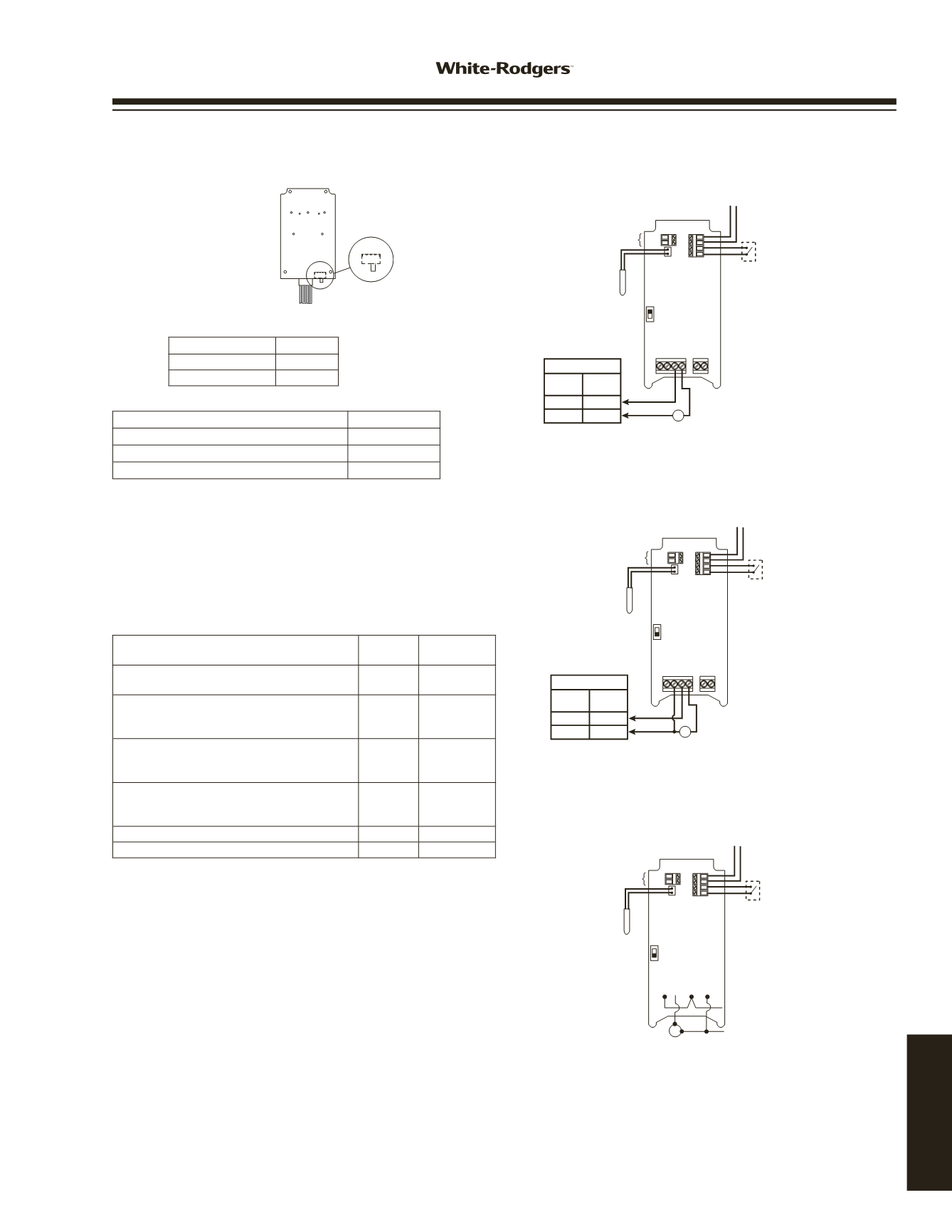
Wiring Instruction Notes
Switch Settings
COOL
HEAT
SW1
COOL
HEAT
SW1
Circuit Board
Inside Cover
Switch SW1 must be set for system mode as shown:
SW1
Refrigeration
Cool
Heating
Heat
Switch SW2 must be set for applications as shown:
SW2
Line Voltage (Power Stealing)
PS
Line Voltage (Non Power Stealing)
Non PS
24 VAC (Non Power Stealing)
Non PS
Power Stealing
Power Stealing is an electronic design within the control that
can eliminate the need to connect a neutral line to power the
control. The control receives power from the unit it is control-
ling. Power Stealing saves time and money by often eliminat-
ing the labor to run a neutral wire to the control for power.
See compatibility chart below for certain limitations.
Power Stealing Compatibility Chart
Application
Power
Stealing
Non-Power
Stealing
Line Voltage, replacing existing control that
has a common wire
Yes
Yes
Line Voltage, with load greater than 2.5
amps, without Defrost timer or other power
interruption circuit, with or without alarm
Yes
Yes
Line Voltage, with load greater than 2.5
amps, with Defrost timer of other power
interruption circuit, no alarm
See
Note 1
Yes
Line Voltage with load greater than 2.5
amps, with Defrost timer or other power
Interruption circuit, with alarm
No
Yes
Line Voltage with load less than 2.5 amps
No
Yes
24 VAC Application
No
Yes
NOTE 1:
During defrost or time when load circuit is broke,
display will be blank because power has been
interrupted to the control. All menu settings and
setpoint will be restored when power is returned.
* NTC – Negative Temperature Coefficient
PTC – Positive Temperature Coefficient
NOTE: Only one sensor (PTC or NTC) may be connected.
Sensor must meet specific temperature vs. resistance
specifications.
Fig. 4 Line Voltage Application
(Non-Power Stealing)
SW2
PTC
BIN
GND
ALARM
NTC
PS
NC
NEUT
LINE
LOAD
24 VAC
TH TR
Binary Input
(Gold Plated
Contacts)
NTC*
Temperature
Sensor
PTC*
Temperature
Sensor
120 VAC
Hot
Neutral
L1
L2
208/240
VAC
Voltage Input
Load
NON
PS
Alarm Output
For optional connection
to customer alarm equipment
24 VAC (Block not used)
TH - Thermostat Hot
TR - Thermostat Return
Fig. 5 24 VAC Applications
(Non-Power Stealing)
SW2
PTC
BIN
GND
ALARM
NTC
PS
Binary Input
(Gold Plated
Contacts)
Note: Do not use Output
Relay to control Line Voltage
when using 24 VAC Power
NTC*
Temperature
Sensor
PTC*
Temperature
Sensor
NC
NEUT
LINE
LOAD
24 VAC
TH TR
NON
PS
Alarm Output
For optional connection
to customer alarm equipment
24 VAC
TH - Thermostat Hot
TR - Thermostat Return
NC contact
operates opposite
of load contact
PTC
BIN
GND
ALARM
NTC
SW2
PS
NON
PS
NC
NEUT
LINE
LOAD
24 VAC
TH TR
Alarm Output
For optional connection
to customer alarm equipment
Binary Input
(Gold Plated
Contacts)
24 VAC (Block not used)
TH - Thermostat Hot
TR - Thermostat Return
NTC*
Temperature
Sensor
PTC*
Temperature
Sensor
Fig. 3 Line Voltage Application
(Power Stealing)
120 VAC
Hot
Neutral
L1
L2
208/240
VAC
Voltage Input
Load
(See "Special Note"
in "Operation Section"
for Alarm)
OPTION SWITCH SETTING
AND WIRING
16E09-101
www.white-rodgers.com199
TECHNICAL HELP