


 183 / 221

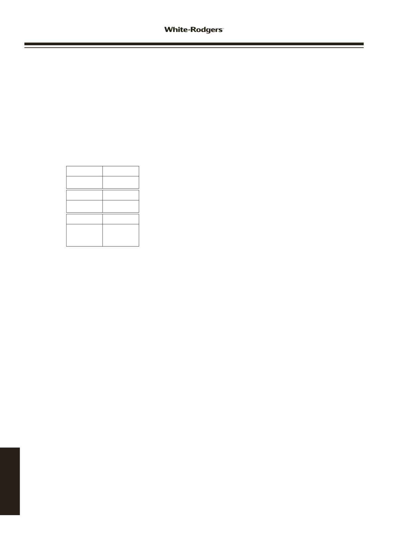
HEAT delay-
to-fan-off:
Set switch
#3 #4
60 sec.
90 sec.
120 sec.
180 sec.*
On On
Off On
On Off
Off Off
COOL delay-
to-fan-off:
Set switch
#1
45 sec.*
90 sec.
On
Off
HEAT delay-
to-fan-on:
Set switch
#2
30 sec.*
45 sec.
On
Off
OPTION SWITCH POSITIONS
* Factory setting
The 50A55-843 is an automatic gas interrupted ignition
control that employs a microprocessor to continually monitor,
analyze, and control the proper operation of the gas burner,
inducer, and fan.
Signals interpreted during continual surveillance of the ther-
mostat and flame sensing element initiate automatic ignition
of the burner, sensing of the flame, and system
shut-off during normal operation.
OPTION SWITCHES
The option switches on the 50A55-843 control are used to
determine the length of the cool delay-to-fan-off, heat delay-
to-fan-on and heat delay-to-fan-off periods. The following
table shows the time periods that will result from the various
switch positions.
HEAT MODE
In a typical system, a call for heat is initiated by closing the
thermostat contacts. This starts the 50A55 control’s heating
sequence. The inducer blower and optional humidifier are
energized and the ignitor is powered within one second.
This controller has an adaptive algorithm that adjusts the du-
ration of the ignitor warm-up, to extend ignitor life. Upon initial
application of power, the warm-up time is 17 seconds. The
ignitor on-time will then be increased or decreased depend-
ing on whether or not flame is achieved. The warm-up time
is limited to a maximum of 21 seconds. During the first 64
warm-up periods following power-up, the warm-up time may
not be less than 17 seconds.
Upon a call for heat, if the warm-up time has not been locked,
it will be decreased by one second. This reduction of the
ignitor on-time will continue until flame fails to be achieved
(resulting in a retry).
In the event of a retry, the warm-up time will be increased by
two seconds and locked in at that duration. Once the warm-
up time is locked, it remains fixed until another call for heat
results in a retry, in which case the warm-up time is again
increased by two seconds and remains locked.
In the event of two successive retry attempts, the warm-up
time will be unlocked and set to 21 seconds. If flame is then
achieved, the warm-up time will begin adapting again with
the next call for heat. If, however, this third attempt fails to
achieve flame, the control will go into system lockout.
At the end of the ignitor warm-up time, both valves in the
36E manifold gas valve are opened. Flame must be detected
within 4 seconds.
See installation instructions for more system sequence detail.
COOL MODE
In a typical system, a call for cool is initiated by closing the
thermostat contacts. This energizes the 50A55 control and
MANUAL FAN ON MODE
If the thermostat fan switch is moved to the ON position, the
circulator fan (cool speed) and optional electronic air cleaner
are energized. When the fan switch is returned to the AUTO
position, the circulator fan and electronic air cleaner (optional)
are de-energized.
SYSTEM LOCKOUT FEATURES
When system lockout occurs, the gas valve is de-energized,
the circulator blower is energized at heat speed, and, if flame
is sensed, the inducer blower is energized. The diagnostic
indicator light will flash or glow continuously to indicate
system status. (
System lockout will never override the
precautionary features
.)
To reset the control after system lockout,
do one of the
following:
1. Interrupt the call for heat or cool at the thermostat for at
least one second but less than 20 seconds (if flame is
sensed with the gas valve de-energized, interrupting the
call for heat at the thermostat will
not
reset the control).
2. Interrupt the 24 VAC power at the control for at least one
second. You may also need to reset the flame rollout
sensor switch.
3. After one hour in lockout, the control will automatically
reset itself.
DIAGNOSTIC FEATURES
The 50A55-843 control continuously monitors its own
operation and the operation of the system. If a failure occurs,
the LED will indicate a failure code as shown below.
If the
failure is internal to the control, the light will stay on
continuously. In this case, the entire control should be
replaced, as the control is not field-repairable.
If the sensed failure is in the system (external to the control),
the LED will flash in the following flash-pause sequences to
indicate failure status (each flash will last approximately 0.25
seconds, and each pause will last approximately 2 seconds).
1 flash, then pause
System lockout
2 flashes, then pause Pressure switch stuck closed
3 flashes, then pause Pressure switch stuck open
4 flashes, then pause Open limit switch
5 flashes, then pause Open rollout switch
6 flashes, then pause 115 Volt AC power reversed /
Improper ground
7 flashes, then pause Low flame sense signal
Continuous flashing
Flame has been sensed when
(no pause)
no flame should be present (no
call for heat)
The LED will also flash once at power-up.
WIRING AND
CONFIGURATION
50A55-843
Trane application
- Jumper wire 151-2906 (provided with
control) must be installed on the furnace from R01 to R02 of
the 12-pin connector.
the compressor. The cool delay-to-fan-on period begins. After
the delay period ends, the optional electronic air cleaner is
energized, and the circulator fan is energized at cool speed.
After the thermostat is satisfied, the compressor is de-
energized and the cool mode delay-to-fan-off period begins.
After the delay-to-fan-off period ends, the circulator fan and
electronic air cleaner (optional) are de-energized.
www.white-rodgers.com184
TECHNICAL HELP