
R
C
G
W
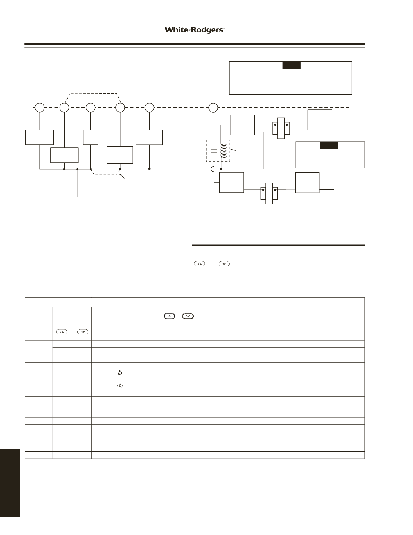
Typical wiring diagram for two transformer single stage systems with safety circuits in BOTH systems
Changeover
Relay*
Y
O/B
Compressor
Contactor
* Changeover Relay is energized in COOL when O/B switch is in the “O” position
Changeover Relay is energized in HEAT when O/B switch is in the “B” position
Heat
Relay
Fan
Relay
Optional
TWO COMMONS MUST
BE JUMPERED TOGETHER!
24 VAC
120 VAC
HOT
NEUTRAL
THERMOSTAT
SYSTEM
HOT
NEUTRAL
120 VAC
Limit or
Safety
Switches
Limit or
Safety
Switches
Limit or
Safety
Switches
24 VAC
Limit or
Safety
Switches
COMMON
COMMON
Auxiliary
Heating
Transformer
(Class II
Current Limited)
Heat Pump Transformer
(Class II Current Limited)
24 VAC
ACCESSORY
RELAY N.O.
CONTACT
Polarity must be observed. If the HOT side of the
second transformer is jumpered to the COMMON side
of the first transformer a short will be made. Damage
to equipment will occur when power is restored.
NOTE
The accessory relay scheme
is required when safety
circuits exist in both systems.
NOTE
Optional Jumper for
Single Stage Heat Pump
1F80-0224/1F86-0244
1F80-0261/1F87-0261
CONFIGURATION MENU
Menu
Reference
Number
Press
Key
Displayed
Factory (Default)
Press
or
to
select from listed options
COMMENTS
1
and
SS
HP
Select Single Stage (SS) or
Heat Pump (HP, 1 compressor)
2
RUN/HOLD*
(OFF) CS
On
Select Cool Savings Feature On or OFF
RUN/HOLD*
(3) CS
1, 2, 3, 4, 5, 6
If CS selected On, selects Cool Savings value
3
RUN/HOLD*
(On) E
OFF
Select Energy Management Recovery On or OFF
4
RUN/HOLD*
(ME)
CR ( )
FA, SL
Select Adjustable Anticipation, cycle rate,
Heat Single Stage
5
RUN/HOLD*
(FA)
CR ( )
SL
Select Adjustable Anticipation, cycle rate,
Cool Single Stage
6
RUN/HOLD*
(OFF) CL
On
Select Compressor lockout OFF or On
7
RUN/HOLD*
(On) L
OFF
Select Display Light On or OFF
8
RUN/HOLD*
Temp
(0 HI)
4 LO to
4 HI
Select temperature display adjustment higher or lower
9
RUN/HOLD*
o
F
o
C
Select
o
F /
o
C Display (temperature units in Fahrenheit or Celsius)
10
RUN/HOLD*
(OFF)
Change Filter
On
Select filter replacement indicator OFF or On
RUN/HOLD*
Change Filter
(200 h)
25 to 1975
If Change Filter selected On, selects time interval for Change Filter
Indicator. (in 25 hour increments)
11
RUN/HOLD*
Returns to normal operation
*Press
RUN/HOLD
to advance to next item or
TIME
to move backwards to previous item
TYPICAL WIRING
AND CONFIGURATION
The configuration menu allows you to set certain thermostat operating characteristics to your system or personal requirements.
To enter the menu: Set your thermostat to OFF and press the
and
buttons simultaneously. The display will show the
first item in the configuration menu. Press RUN/HOLD to change to the next menu item or press TIME to go backwards to the
previous item in the menu. To exit the menu and return to the program operation, press PRGM. If no keys are pressed within
fifteen minutes, the thermostat will revert to normal operation.
INSTALLER/CONFIGURATION MENU
www.white-rodgers.com156
TECHNICAL HELP


