
N/A
Step
Press Button(s)
COMMENTS
Press or to select:
Displayed
(Factory Default)
HOLD
(0:00)
0 to 8 hrs (in
15 minute increments)
2
(FA)
SL
Select temporary Hold time
N/A
N/A
E
(ON)
OFF
4
5
LOC
(OFF)
ON
0 HI
(0)
4 LO
to
4 HI
°(F)
°C
Returns to normal operation
Returns to normal operation
6
7
Select Energy Management Recovery
OFF
or
ON
Select Compressor lockout
OFF
or
ON
Select temperature display adjustment higher or lower
Select temperature display to
°F
or
°C
RUN
PRGM
and
RUN
*
*
3
d-L
(ON)
OFF
Select display backlight
OFF
or
ON
*
*
Filter
(000)
0 to 1950 hours
(in 50 hour increments)
Select filter replacement run time
*
*
*
Select
FA
or
SL
(Fast or Slow) heating cycle rate
Configuration Menu
N/A
Step Step
2 2
N/A
4
5
6
7
8
3 3
1
1
Step
2
4
4
5
5
6
6
7
7
8
8
9
9
3
1
1
SYSTEM switch must be OFF to configure thermostat
options
Set
SYSTEM
switch to
OFF
Set
SYSTEM
switch to
HEAT
or
COOL
1
N/A N/A
N/A N/A
N/A N/A
Step
2
4
N/A
5
6
7
8
3
1F80-241
1F80-361
1F86-241
1F86-344
1F87-361
N/A
1
N/A
*9
Step
2
4
5
N/A
6
7
8
3
*1F80-240
1
N/A
8
Step
2
N/A
N/A
4
5
6
7
3
1F80-224
* 1F80/1F87 - Press
HOLD
to advance to next item or
TIME
to move backwards to previous item
1F86 - Press and
to advance to next item
1F80-240 is HEAT only
RH
24 VAC
120 VAC
Hot
Neutral
THERMOSTAT
SYSTEM
G
W
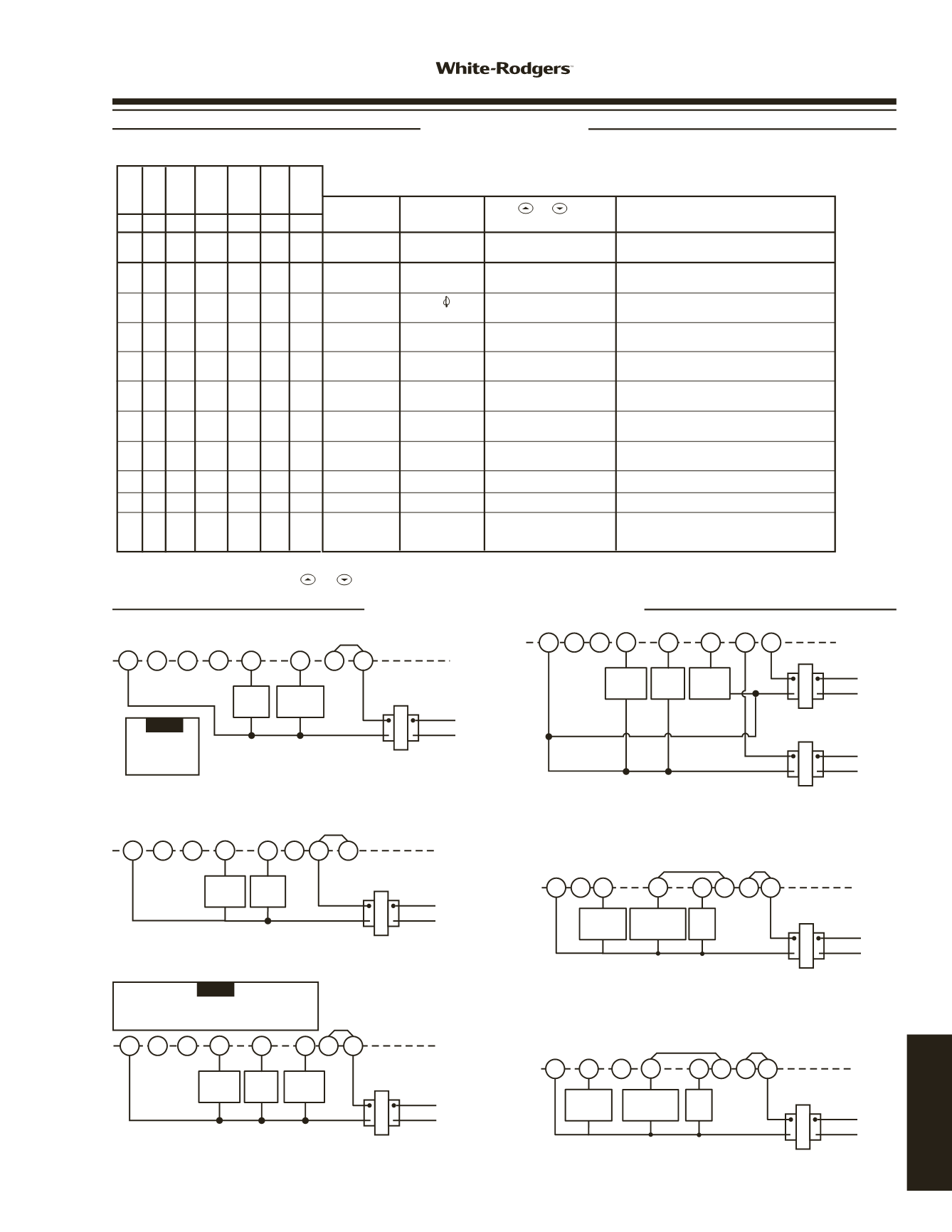
Heat only, 3-wire, single transformer systems
TRANSFORMER
Heating
System
Fan
Relay
Y
C ‡
RC
JUMPER
WIRE
O B
For 1F80-361 and
1F86-344 2-wire
Heat only, attach
to RH and W.
NOTE
RH
Y
24 VAC
120 VAC
Hot
Neutral
TRANSFORMER
THERMOSTAT
SYSTEM
G W
Cool only, 3-wire, single transformer systems
Cooling
System
Fan
Relay
RC
O B C ‡
JUMPER
WIRE
RH
Y
24 VAC
120 VAC
Hot
Neutral
THERMOSTAT
SYSTEM
G
W
Heat/cool, 4-wire, single transformer systems
TRANSFORMER
Heating
System
Fan
Relay
Cooling
System
RC
JUMPER
WIRE
O
C ‡ B
RED
jumper wire (provided with thermostat)
must
be
connected between thermostat
RH
and
RC
terminals
for proper thermostat operation with this system.
NOTE
RH
Y
24 VAC
120 VAC
Hot
Neutral
THERMOSTAT
SYSTEM
G
W
Heat/cool, 5-wire, two-transformer systems
HEATING
TRANSFORMER
Heating
System
Fan
Relay
Cooling
System
RC
24 VAC
120 VAC
Hot
Neutral
COOLING TRANSFORMER
O B C ‡
RH
Y
24 VAC
120 VAC
Hot
Neutral
THERMOSTAT
SYSTEM
G W
Heat pump with reversing valve energized in COOL
TRANSFORMER
Reversing
Valve*
RC
O B C ‡
JUMPER
WIRE
Compressor
Contactor
JUMPER
WIRE
* Reversing valve is energized when the
system switch is in the COOL position
Fan
Relay
RH
Y
24 VAC
120 VAC
Hot
Neutral
THERMOSTAT
SYSTEM
G W
Heat pump with reversing valve energized in HEAT
TRANSFORMER
Reversing
Valve*
RC
O B C ‡
JUMPER
WIRE
Compressor
Contactor
JUMPER
WIRE
* Reversing valve is energized when the
system switch is in the HEAT position
Fan
Relay
The following table allows you to customize the options on your Comfort-Set thermostat.
1F80-224 / 1F80-240 / 1F80-241 / 1F80-361
1F86-241 / 1F86-344 / 1F87-361
CONFIGURATION AND
TYPICAL WIRING DIAGRAMS
CONFIGURATION
TYPICAL WIRING DIAGRAMS
www.white-rodgers.com159
TECHNICAL HELP


