
FAN CONTROL CENTER
RELAY & TRANSFORMER
90-112 THRU 90-130
FAN CONTROL CENTER
Transformer and Relay Combination for Easy Installation on a
4
”
x 4
”
Junction Box
SPECIFICATIONS
Agency . . . . . . . . . . . . . . . . . . . . . . . . . . . U.L. file fan center E73641
FEATURES
• Line voltage connections pre-wired.
• Energy limiting class II transformer design.
• Color coded pre-stripped leads.
• Low voltage connections on terminal board.
Approximate Overall Dimensions
2
1
/
8
”
x 1
7
/
8
”
x 2
1
/
4
”
90-112 THRU 90-130
U.L. Recognized
Model Number
Replaces Relay On
Description
90-340
90-112, 90-113, 90-117 DPDT Universal
90-118E, 90-119, 90-130 Plug-in Relay
REPLACEMENT RELAY FOR FAN CONTROL CENTER
90-340
Transformer
Contact Ratings
Model
Mars
Primary
Secondary
120 VAC (amps)
240 VAC (amps)
Number Number Voltage Hz Connections Voltage VA Connections Relay Full Load Locked Rotor Full Load Locked Rotor
90-112
24010 120
60 Color coded 24V 40 Terminal board DPDT 13.8
82.8
6.9
41.4
leads,
with 5 screw
pre-stripped
terminals
90-113
24013 120
60 Color coded 24V 40 Terminal board SPDT 13.8
82.8
6.9
41.4
leads,
with 5 screw
pre-stripped
terminals
90-118E
24012 120
60 Color coded 24V 40 Terminal board SPNO /
13.8
82.8
6.9
41.4
leads,
with 5 screw SPNC
pre-stripped
terminals
90-130
24010 120 /
50 / 60 Color coded 24V 40 Terminal board DPDT 13.8
82.8
6.9
41.4
208 / 240
leads,
with 5 screw
pre-stripped
terminals
BROWN N.C.
RED
BLACK
RED N.C.
CONTACT
COMMON
CONTACT
COMMON
CONTACT
COMMON
CONTACT
COMMON
CONTACT
COMMON
BLACK
C
Y
G
WHITE
W
R
COM
BLACK N.O.
COIL
BLACK
Y
RED N.O.
VIOLET
C
G
W
COIL
R
BLACK
G
BLACK
R
RED/YEL N.O.
120 V
60 HZ
90-112
120 V
60 HZ
90-118E
G
120 V
60 HZ
WHITE
R
W
C
208/240 V
60 HZ
Y
W
G
WHITE
R
W
BLACK
BROWN N.C.
BLACK
BROWN N.C.
RED N.O.
Y
C
COIL
240
RED
208
BLUE
WHITE
90-119
Y
BLACK
YELLOW N.C.
COIL
90-113
RED N.O.
120 V
60 HZ
BLACK
C
RED
COIL
90-117
RED N.O.
*
* Black is common with respect to transformer
winding, not external circuit.
Note:
Record the lead wire color with it's
corresponding terminal for future reference.
Unused transformer input leads must be
insulated.
120
WHITE
BLACK
BROWN N.C.
BLACK
COIL
VIOLET
CONTACT
COMMON
CONTACT
COMMON
YELLOW N.C.
RED/YEL N.O.
240
RED
BLUE
Y
W
R
RED N.O.
208
120/208/240 V 50/60 HZ
60 HZ
C
G
COM
90-130
*
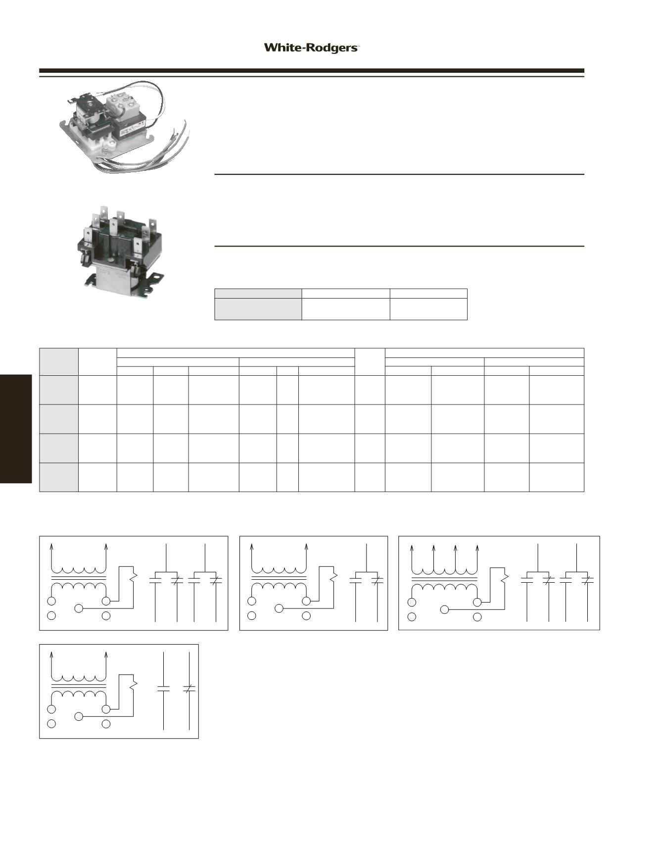
When the fan relay transformer is energized and the thermostat completes the con-
nection from R to G the fan relay coil energizes. Line voltage power applied to contact
common path travels to selected blower speed tap. Additional terminal Y and W are
isolated tie point terminals to connect thermostat wiring to compressor and furnace
(if required).
www.white-rodgers.com96
TRANSFORMERS /
RELAYS


