
GOODMAN
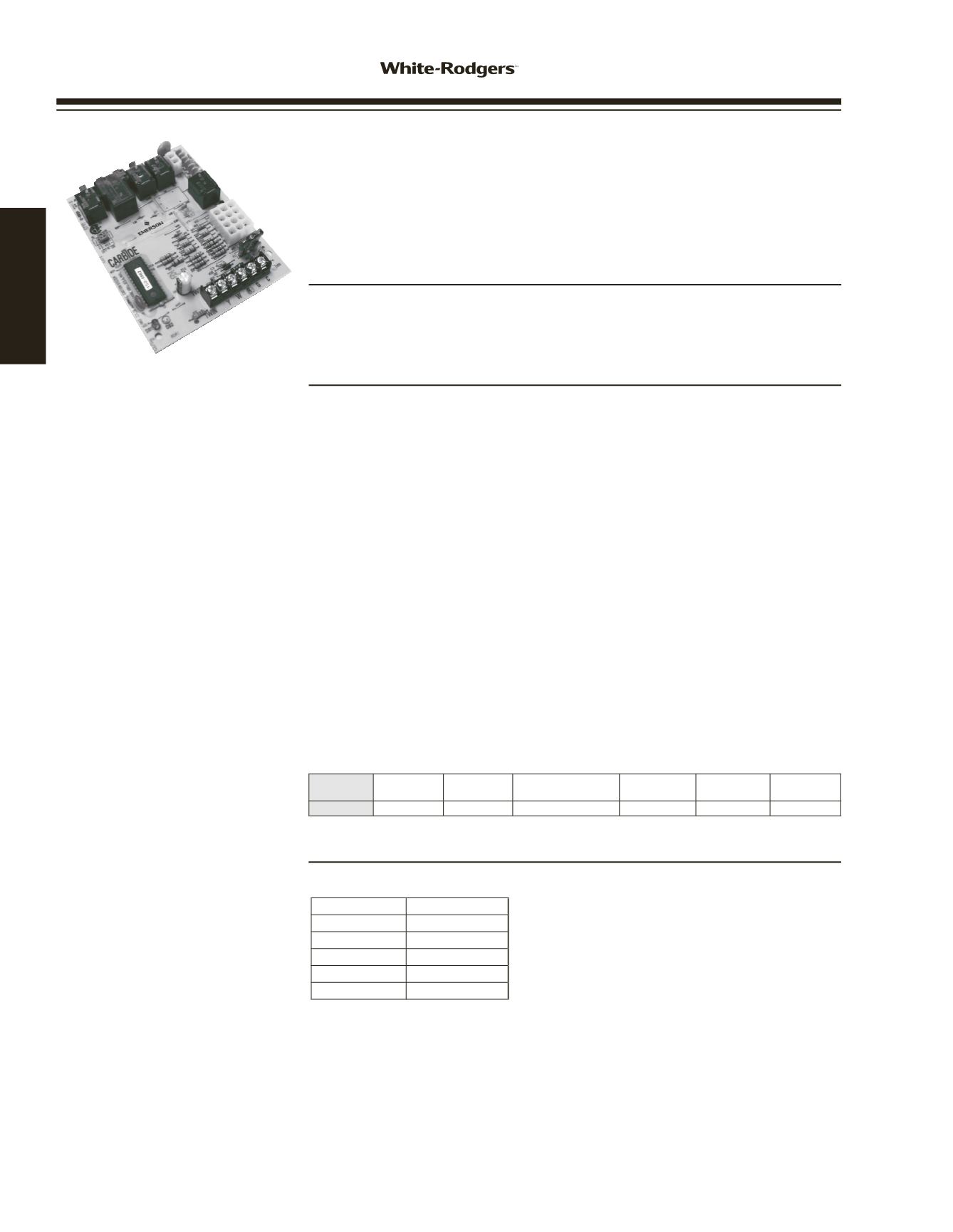
INTEGRATED HSI MODULE
DIRECT
REPLACEMENT
50A55-743
50A55-743 GOODMAN SILICON CARBIDE SINGLE
STAGE INTEGRATED HSI FURNACE CONTROL
Controls Gas Valve, Ignitor, Blower, Inducer, Humidifier
(Both 120V & 24V Input), and Air Cleaner. Replaces OEM
Goodman and White-Rodgers Models
FEATURES
• Includes flash code diagnostics.
• Twinning connection.
• Fused to protect low voltage system transformer
SPECIFICATIONS
Operating Temperature . . . . . . . . . -40 to 176°F
Humidity Range . . . . . . . . . . . . 5% to 93% RH (non-condensing)
Mounting . . . . . . . . . . . . . . . Snap in standoffs
Electrical Ratings @ 77°F (25°C)
Input Voltage . . . . . . . . . . . . . 25 VAC 50 / 60 Hz
Maximum Input Current @ 30 VAC . . . . . 0.45 amp
Relay Load Ratings
Valve Relay . . . . . . . . . . . . . . 1.5 amp @ 25 VAC 50 / 60 Hz 0.6 pf
Ignitor Relay . . . . . . . . . . . . . 6.0 amp @ 120 VAC 50 / 60 Hz
Inducer Relay . . . . . . . . . . . . . 2.2 FLA-3.5 LRA @ 120 VAC
Circulator Relay . . . . . . . . . . . . 14.5 FLA-25.0 LRA @ 120 VAC
Flame Current Requirements
Minimum current to insure flame detection . . 1 uA DC
Maximum current for non-detection . . . . . 0.10 uA DC
Maximum allowable leakage resistance . . . 100 M ohms
Timing Spec (@ 60 Hz) maximum
Flame establishing time . . . . . . . . . 0.8 sec
Flame failure response time . . . . . . . 2.0 seconds
NOTE
: At 50 Hz, all timing specifications should be increased by 20%.
Model
Number
Pre-Purge
Time
Heat
Delay On
Heat Delay
Off Sec.
Cool Delay
On Sec.
Cool Delay
Off Sec.
Post
Purge
50A55-743
15 seconds
30
90 / 120 / 150 /180
5
45
15 sec
50A55-743 Replaces:
0130F00005
PCBBF110
0130F00005S PCBBF110S
50A55-289
PCBBF112
50T55-289
PCBBF112S
B1809926
PCBBF123
B1809926S
PCBBF123S
CROSS REFERENCE
NOTE
: Can also use Universal Kit 50M56U-843
www.white-rodgers.com48
HEATING


