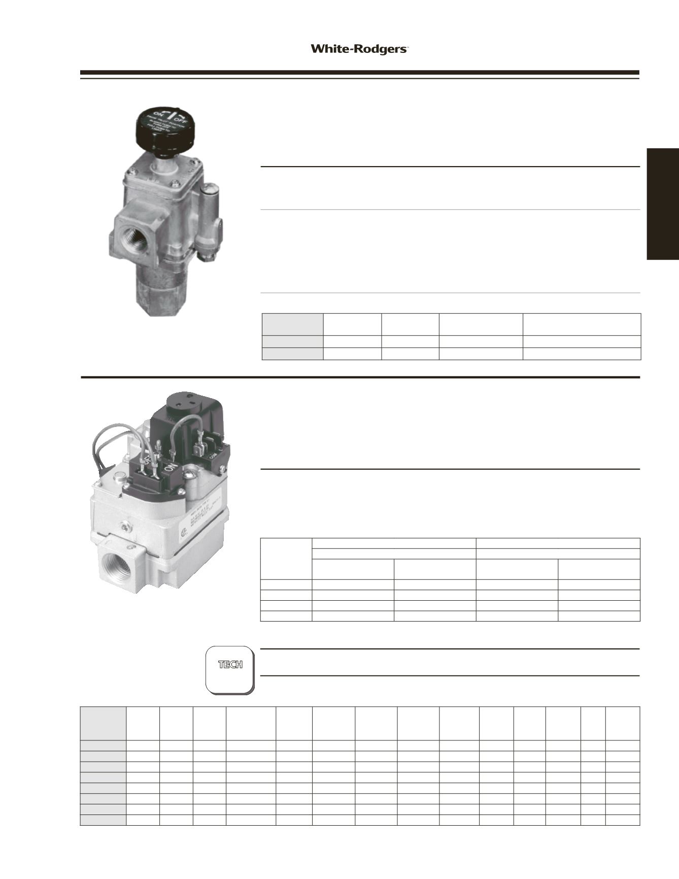

764 / 36C SERIES
GAS VALVES
GAS BURNER
CONTROLS
764-702
764 SERIES THERMOCOUPLE OPERATED
GAS PILOT SAFETY/GAS FIREPLACE VALVES
In Line Appliance Control with 100% Shut Off
FEATURES / SPECIFICATIONS / PART AND ACCESSORIES
• Redesigned to include 100 PSI protection, inlet screen and inlet pipe stop.
• Optional rear inlet tapped and plugged.
• May be mounted horizontal, vertical and 90° from horizontal (multipoise).
Electrical Rating . . . . . . . . . . . . . . . . . . . . 20 to 30 mV (Thermocouple)
Regulator Adjustment Range . . . . . . . . . . Non-regulated
Maximum Pressure Rating . . . . . .
1
/
2
PSI (14.0
”
W.C.)
Ambient Operating Range . . . . . . -40 to 250°F
Swing Radius . . . . . . . . . . . . . . . . . . . . . . 2.5
”
Agency . . . . . . . . . . . . . . . . . . . . . . . . . . . C.S.A. approved
• F42-0895 — Replacement knob
Model Number Coil Voltage
Inlet-Outlet
Size
Capacity A.G.A.
Standard Gas
➀
Electrical Connections
764-702
20 to 30 mV
3
/
8
”
x
3
/
8
”
132,000
Thermocouple
764-742
20 to 30 mV
1
/
2
”
x
1
/
2
”
142,000
Thermocouple
➀
See page 221 for capacities of other gases
?
36C84-912
PAGES
172–175
36C Cycle PILOT GAS VALVES
With Redundant Pilot Solenoid Main Gas Regulator, Integral Gas
Pressure Switch and Electrical Connection on the Gas Valve for
Mercury Flame Sensor Connection
SPECIFICATIONS
Electrical Rating . . . . . . . . . . . . . . . . . . . . 0.6 amps
End to End Dimensions . . . . . . . 3
15
/
16
”
Ambient Operating Range . . . . . . -40 to +175°F (-40 to 79°C)
Maximum Pressure Rating . . . . . .
1
/
2
PSI (14.0
”
W.C.)
Agency . . . . . . . . . . . . . . . . . . . . . . . . . . . C.S.A. approved
PARTS AND ACCESSORIES
See end of this section for parts and accessories
TECHNICAL HELP
Wiring Diagrams . . . . . . . . . . . See pages 172–175
Pipe Size
1” Pressure Drop Capacity
Rated Range of Regulation
BTU/HR
BTU/HR
STD. NAT GAS
1000 BTU/CU. FT.
LP GAS
2500 BTU/CU. FT.
STD. NAT GAS
1000 BTU/CU. FT.
LP GAS
2500 BTU/CU. FT.
1/2 X 3/8
100,000
162,000
15,000-100,000
15,000-162,000
1/2 X 1/2
230,000
372,600
30,000-290,000
30,000-469,000
1/2 X 3/4
230,000
372,600
30,000-290,000
30,000-469,000
3/4 X 3/4
280,000
453,600
50,000-400,000
50,000-648,000
Model
Number
Coil
Voltage
Gas
Type
Pipe
Size
Opening
Characteristic
Regulator
Setting
Regulator
Adjustment
Range
Convertible
Nat. / LP
LP
Conversion
Kit
Included
Line
Interrupter
Flow
Direction
Reducer
Bushing
Kit
Inlet
Pressure
Tap
Side
Taps
Internal
Wiring
See
Figure
➀
36C84-912
24 VAC Nat./LP
3
/
4
x
3
/
4
Fast Open 3.5
”
2.5
”
–5.0
”
Yes
Yes
No Str. Thru Yes
Yes No
7
36C84-913
24 VAC Nat./LP
3
/
4
x
3
/
4
Fast Open 3.5
”
2.5
”
–5.0
”
Yes
Yes
No Str. Thru Yes
Yes No 12
36C84-921
24 VAC Nat./LP
3
/
4
x
3
/
4
Fast Open 3.5
”
2.5
”
–5.0
”
Yes
Yes
No Str. Thru Yes
Yes No
7
36C84-923
24 VAC Nat./LP
3
/
4
x
3
/
4
Fast Open 3.5
”
2.5
”
–5.0
”
No
No
No Str. Thru No
Yes No 14
36C84-926
24 VAC Natural
3
/
4
x
3
/
4
Fast Open 3.5
”
2.5
”
–5.0
”
No
No
No Str. Thru Yes
No No
4
36C84-945
24 VAC Nat./LP
3
/
4
x
3
/
4
Fast Open 3.5
”
2.5
”
–5.0
”
Yes
Yes
No Str. Thru Yes
Yes No
8
36C94-906
24 VAC Natural
3
/
4
x
3
/
4
Slow Open 3.5
”
2.5
”
–5.0
”
No
No
No Str. Thru Yes
No No
7
36C94-907
24 VAC Nat./LP
3
/
4
x
3
/
4
Slow Open 3.5
”
2.5
”
–5.0
”
Yes
Yes
No Str. Thru Yes
No No
4
➀
Wiring diagrams – see pages 172–175
NOTE
: -9XX series replaces -4XX series. Knob replaced with an ON-OFF switch.
www.white-rodgers.com39
HEATING


