


 206 / 221

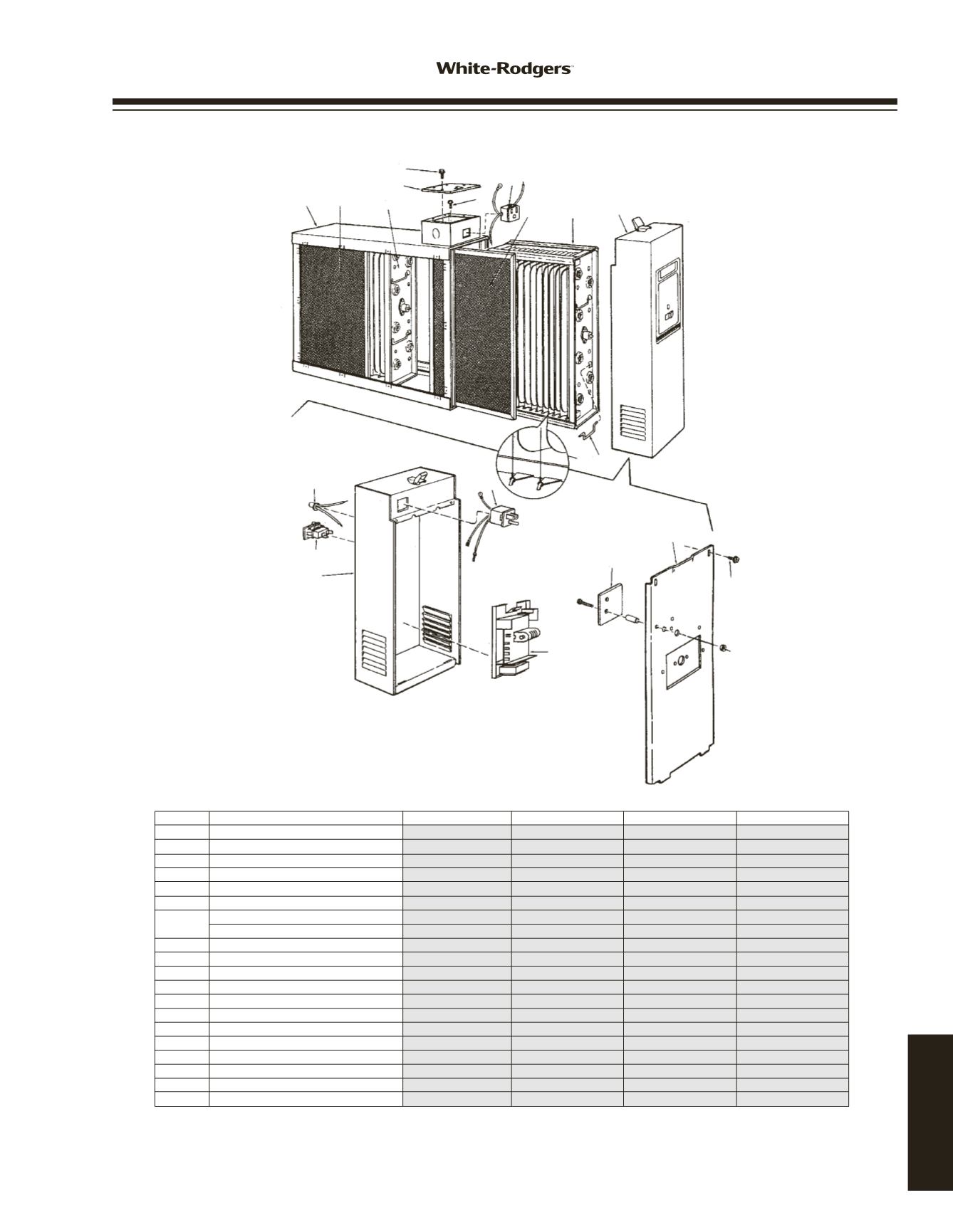
PARTS VIEW DIAGRAM
1 2 3
5
4
5
5
6
2 3 7
89
13
14
12
11
10
15
17
SST SERIES
* Standard Hardware Item
• Two Required
†
Not Shown
††
Kit converts -100 models to Air Flow Switch. -150 models include Air Switch
ITEM NO. DESCRIPTION
SST1000-101 / 151 SST1400-101 / 151 SST1600-101 / 151 SST2000-101 / 151
1 Cabinet
N/A
N/A
N/A
N/A
2 Pre-Filter
• F825-0431
• F825-0432
• F825-0337
• F825-0338
3 Collecting Cell
• F811-0398
• F811-0397
None
• F811-0319
4 Junction Box Cover
None
None
None
None
5 Screw #6 X 3/8 *
–
–
–
–
6 Connector, Female
F818-0053
F818-0053
F818-0053
F818-0053
7 Power Pack Assembly without Air Flow None
None
None
None
Power Pack Assembly with Air Flow None
None
None
None
8 Cell Handle
None
None
None
None
9 Ionizing Wire
F843-0484
F843-0484
F843-0500
F843-0500
10 Light
F844-0130
F844-0130
F844-0130
F844-0130
11 Switch
F876-0202
F876-0202
F876-0202
F876-0202
12 Power Pack, Cabinet Only
N/A
N/A
N/A
N/A
13 Connector, Male
F827-0026
F827-0026
F827-0026
F827-0026
14 Power Supply
F858-1002
F858-1002
F858-1002
F858-1002
15 Cover, Power Pack
None
None
None
None
16 Manual
†
37-6373E
37-6373E
37-6373E
37-6373E
17 Charcoal Filter (with mounting clips)
†
F825-0466
• F825-0467
• F825-0468
• F825-0469
18 Air Flow Switch (monitor kit)
††
F859-0381
F859-0381
F859-0381
F859-0381
Power Cord, 6 ft., 120 V
†
None
None
None
None
www.white-rodgers.com207
TECHNICAL HELP