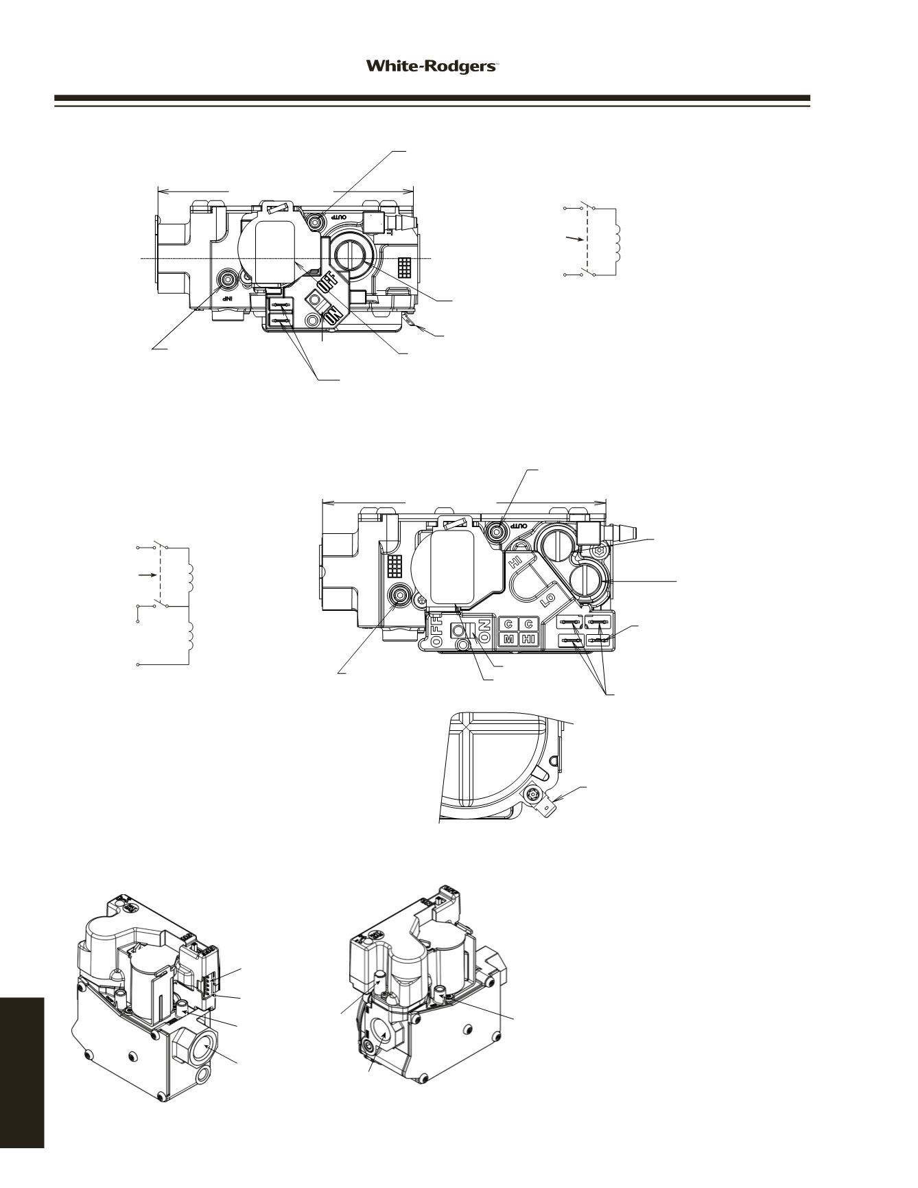

GAS VALVES
36G/J
WIRING
Outlet Pressure Post
.339
Dia. +DFT.
(Set Screw:
3/32”
Hex Head)
Accept
5/16”
ID Hose Connection
Regulator Cover Screw
(Reg. Adj. Beneath This Screw)
3/16”
Ground Terminal
Control I.D. Label
1/4” x .032” THK. Male
Spade Terminals (2)
Inlet Pressure Post
.339 Dia. +DFT.
(Set Screw: 3/32” Hex Head)
Accept 5/16” I.D. Hose
ConnecƟon
4.693”
Inlet to Outlet
On/Off
Switch
Fig. 1 - Single Stage Valve Features, Terminals and Wiring
Fig.3 -
36J27 Modulating Valve Features
OUTLET
PRESSURE
TAP POST
VALVE OUTLET
REGULATOR
VENT
ELECTRICAL
5 PIN CONNECTOR
PIN 1
LOCATION
INLET
PRESSURE
TAP POST
VALVE INLET
Electrical 5 PIN Connector Pin Out
PIN 5 - TH - Main Valve 24 VAC (top pin,
with the cover pointing up)
PIN 4 - TR - Ground
PIN 3 - TX - Communication to IFC
PIN 2 - RX - Communication to Stepper
PIN 1 - TH - Board 24VAC (bottom pin,
with the cover pointing up)
Outlet Pressure Post
Set Screw:
3/32”
Hex Head
(
.339
Dia. + DFT.)
Accepts
5/16”
Hose Connection
Low Fire Regulator
Cover Screw
(Reg. Adj. Beneath
the Screw)
3/16”
x
.032”
Thick Male
SpadeTerminal
(1)
1/4”
x
.032”
Thick Male
SpadeTerminals
(3)
3/16” Ground Terminal
Control I.D. Label
Inlet Pressure Post
Set Screw: 3/32” Hex Head
(.339 Dia. + DFT.)
Accepts 5/16” Hose ConnecƟon
4.693”
Inlet to Outlet
On/Off Switch
High Fire Regulator
Cover Screw
(Reg. Adj. Beneath
the Screw)
Fig. 2 -
Two-Stage Valve Features, Terminals and Wiring
On/Off
Switch
Main and
Redundant
Valves
On/Off
Switch
Hi
M
Main and
Redundant
Valves (Low Fire)
2
nd Stage
Valve (High Fire)
C
C
www.white-rodgers.com178
TECHNICAL HELP


