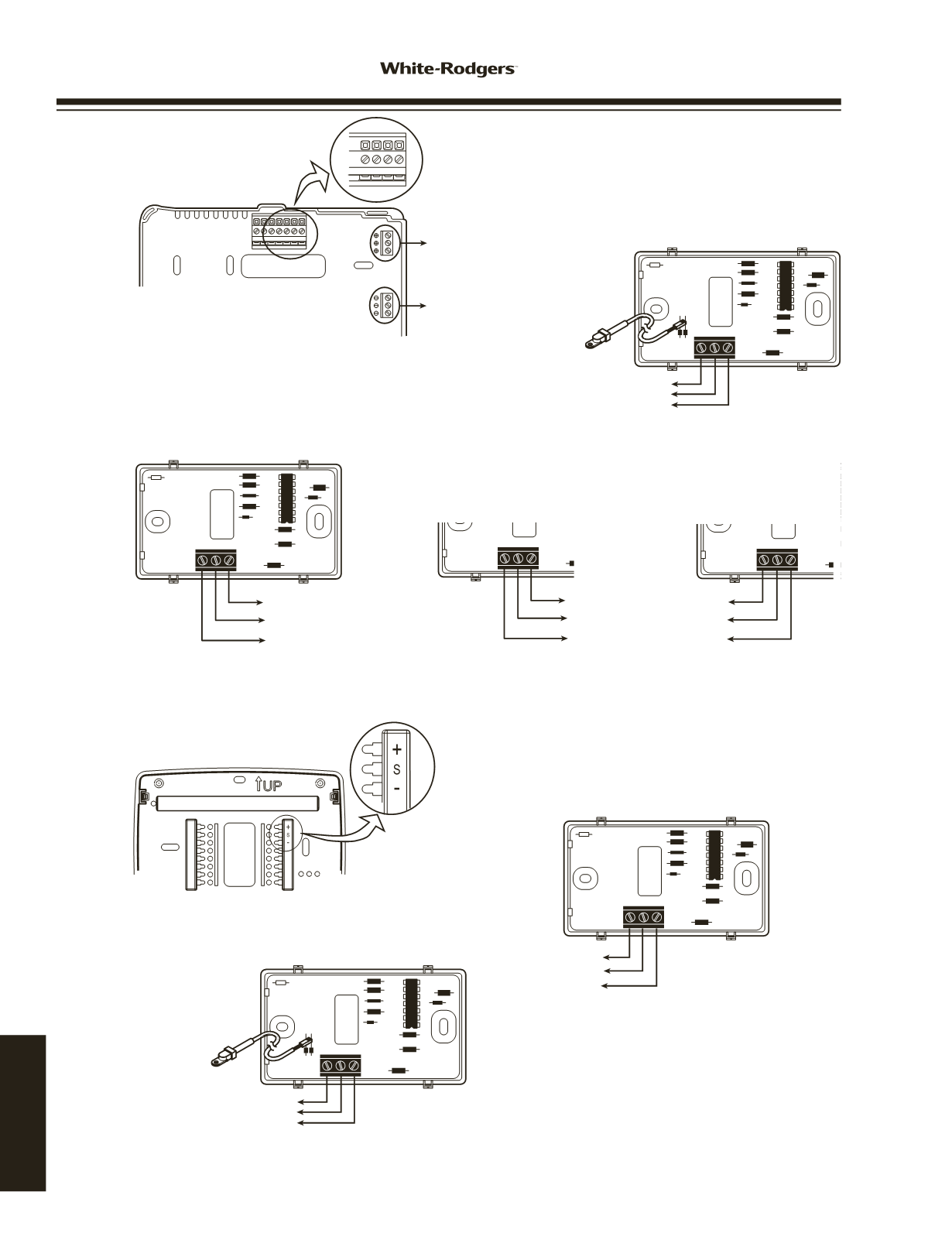

WIRING
WIRED
REMOTE SENSOR
RCE
W2 W1 Y2 Y1 B O G
PH D SASBSCOT
L
W3
A1
E2
P
SA SB SC OT
+ Terminals
- Terminals
Thermostat Subbase
+
S
E2
–
To +
To OT
To -
Outdoor Probe
Remote Outdoor Sensor Base
Note: When using shielded cable, connect shield of 18 or
20 gauge 3 connector cable to - or S3 on thermostat
subbase.
+
S
E2
–
To -
To SA
To +
+
S
E2
–
To -
To SB
To +
+
S
E2
–
To -
To SC
To +
Remote Indoor Sensor A
Remote Indoor Sensor B
Remote Indoor Sensor C
Staging Thermostat Multi-Stage or Heat Pump Indoor/Outdoor Remote Sensor Wiring
(F145-1328/F145-1378)
Single Stage (1F97-1277) TouchscreenThermostat Indoor/Outdoor Remote Sensor Wiring
(F145-1328/F145-1378)
Thermostat Subbase
Remote Sensor
Note: When using shielded cable, connect shield of 18 or
20 gauge 3 connector cable to - or S3 on thermostat
subbase.
+
S
E2
–
To + or S1
To S or S2
To - or S3
+
S
E2
–
To +
To OT
To -
Outdoor Probe
Remote Sensor
If connecting
outdoor service
www.white-rodgers.com170
TECHNICAL HELP


