
WIRED
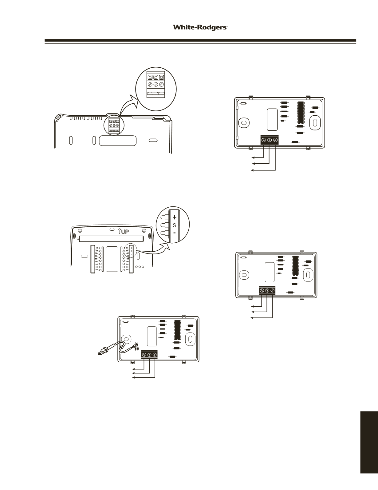
REMOTE SENSORS
WIRING
+
S
E2
–
To + or S1
To S or S2
To - or S3
Thermostat Subbase
+
S
E2
–
To +
To OT
To -
Outdoor Probe
Remote Sensor
Note: When using shielded cable, connect shield of 18 or
20 gauge 3 connector cable to - or S3 on thermostat
subbase.
Remote Outoor Sensor
Staging Multi-Stage or Heat Pump Touchscreen Thermostat (1F95-1277) Indoor/Outdoor Remote
Sensor Wiring (F145-1328/F145-1378)
If connecting
outdoor service
Troubleshooting Chart
e
To function correctly and read temperature accurately, the thermostat must have constant 24-volt power. If the thermostat
temperature is steadily dropping, reading low, or reads 08°° when a remote sensor is installed, it can be traced to one of the
three following conditions.
Condition
Test
Comments
1. Loss of 24-volt power. On models with batteries, remove the batteries and re-install
For the sensor to read correctly,
thermostat. If the display is blank, check heating and cooling the 24-volt system power
must
system to determine why 24-volt power is absent.
be present. Some systems may
require an isolation relay to pro-
vide constant power to the
thermostat. Limit or safety
Single Stage Thermostat Remote Sensor Wiring (F145-1328)
Thermostat Subbase
+
S
E2
–
To + or S1
To S or S2
To - or S3
Remote Sensor
Note: When using shielded cable, connect shield of 18 or
20 gauge 3 connector cable to - or S3 on thermostat
subbase.
S1 S2 S3
S1 S2 S3
or
+ S -
Troubleshooting Chart
To function correctly and read temperature accurately, the thermostat must have constant 24-volt power. If the thermostat
temperature is steadily dropping, reading low, or reads 08° when a remote sensor is installed, it can be traced to one of the
three following conditions.
Condition
Test
Comments
1. Loss of 24-volt power. On models with batteries, remove the batteries and re-install
For the sensor to read correctly,
thermostat. If the display is blank, check heating and cooling the 24-volt system power
must
system to determine why 24-volt power is absent.
be present. Some systems may
require an isolation relay to pro-
vide constant power to the
thermostat. Limit or safety
devices in the equipment can
also cause a power interruption.
2. A broken wire on S1,
Disconn ct s nsor wires at thermostat. Attach a short piece Repair or replace the 3 wire
S2 and S3 or (+, SA, -) (2') of three-wire shielded cable to S1, S2 and S3 or (+, SA,
shielded cable. Be sure the
from the thermostat to -) on the subbase. Bring the remote sensor to the thermostat remote wire run is not parallel
the remote.
location and attach S1, S2 and S3 or (+, S, -) respectively.
to line voltage wires that carry
Reattach thermostat. If the temperature begins to climb
heavy inductive loads, or across
(slowly), it is reading correctly. If it reads correctly with the 2'
fluorescent light ballasts that
length but improperly when attached to the wire run, it
may cause an inductance to be
.tatsomreht eht ot dettimsnart
.nur eriw eht ni tluaf a setacidni
3. A shorted or
Because it is an electronic sensor, there are no Ohm values Replace remote sensor.
damaged remote sensor. to test. If correct conditions as listed in 1 & 2 above and the
temperature stays at or near 08°, it indicates a shorted or
damaged remote sensor.
Note: Digital thermostats and remote sensors acclimate very slowly to temperature change. It may take an hour or more for
the temperature to acclimate to the room temperature from a low temperature reading as outlined above. To expedite the
room temperature display use the reset instructions listed in the installation instructions for the thermostat model you are
working with. When reset, the thermostat will default to a room temperature of 70° and begin sensing room temperature. Be
sure to reconfigure the installer menu for a remote sensor because the reset function may cancel remote sensing.
www.white-rodgers.com169
TECHNICAL HELP


