


 22 / 221

THERMOSTATS
www.white-rodgers.com23
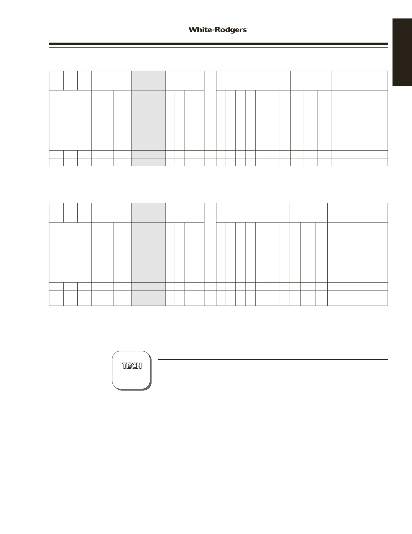
HEAT PUMP THERMOSTATS – 70 SERIES THERMOSTATS
Single
Stage
Multi-
Stage
Heat
Pump
Programs
Model
Applications
Thermostat Power Source*
Selectable Performance
Features
Comfort and
Convenience
Features
Terminals
Stages Heat/Cool
by System
Program
Options
Periods
Per Day
Options
Model
Number
Gas / Oil / Electric
3 Wire Zone Valve
Millivolt Compatible
Humidity Control
(H)-Humidity / (D)-Dehumidify
Auto Changeover
Programmable Fan
Energy Mgt. Recovery
Keypad Lockout
(T)-Total / (P)-Partial
Set-Point Temperature Limits
Adjustable Max/Min
Indoor Remote Sensors
Max. Number + Thermostat
Average and/or Weighted
Outdoor Remote Sensor
Display Size
(Square inches)
Lighted Display
Memory Back-Up
(P)-Permanent / (B)-Battery
2/1 5+2
4
1F72-151
H
3
1.2
3
*** P R, C, W2, EY, O/B, G, L
2/1
Ø
Ø
1F79-111
H
1.2
3
*** P R, C, W2, EY, O/B, G, L
SINGLE STAGE THERMOSTATS – 70 SERIES THERMOSTATS
Single
Stage
Multi-
Stage
Heat
Pump
Programs
Model
Applications
Thermostat Power Source*
Selectable Performance
Features
Comfort and
Convenience
Features
Terminals
Stages Heat/Cool
by System
Program
Options
Periods
Per Day
Options
Model
Number
Gas / Oil / Electric
3 Wire Zone Valve
Millivolt Compatible
Humidity Control
(H)-Humidity / (D)-Dehumidify
Auto Changeover
Programmable Fan
Energy Mgt. Recovery
Keypad Lockout
(T)-Total / (P)-Partial
Set-Point Temperature Limits
Adjustable Max/Min
Indoor Remote Sensors
Max. Number + Thermostat
Average and/or Weighted
Outdoor Remote Sensor
Display Size
(Square inches)
Lighted Display
Memory Back-Up
(P)-Permanent / (B)-Battery
1/1
1/1 5+2
4
1F78-151
3 3
B
3
1.2
3
*** P RC,RH, W, Y,O, B, G
1/1
1/1
Ø
Ø
1F78-144
3 3
B
1.2
3
*** P RC,RH, W, Y,O, B, G
1/1
Ø
Ø
1E78-140
3 3
B
1.2
3
*** P
RH, W
70 SERIES
THERMOSTATS
?
* H = Hardwired (Requires Common)
Heat Pump for Stage 1, and Gas / Oil / Electric for 2nd stage / Emergency
B = Battery Powered
Available in vertical style order 1E78-144/151
*** Optional Continuous Display Light w/ Hardwire connection
pages
162–164
TECHNICAL HELP
1E78-151..............................Wiring Diagrams/Configuration.........See page 162
1F72-151 / 1F79-111..............Wiring Diagrams/Configuration.........See page 163
1F78-144 / 1F78-151............Wiring Diagrams/Configuration.........See page 164
24 VOLT