
All logos, trademarks, part numbers, photos & illustrations are intended solely for identification.
Items offered for sale are not represented to be manufactured by the company that built the original equipment.
132
MAGNETRONS
MICROWAVE
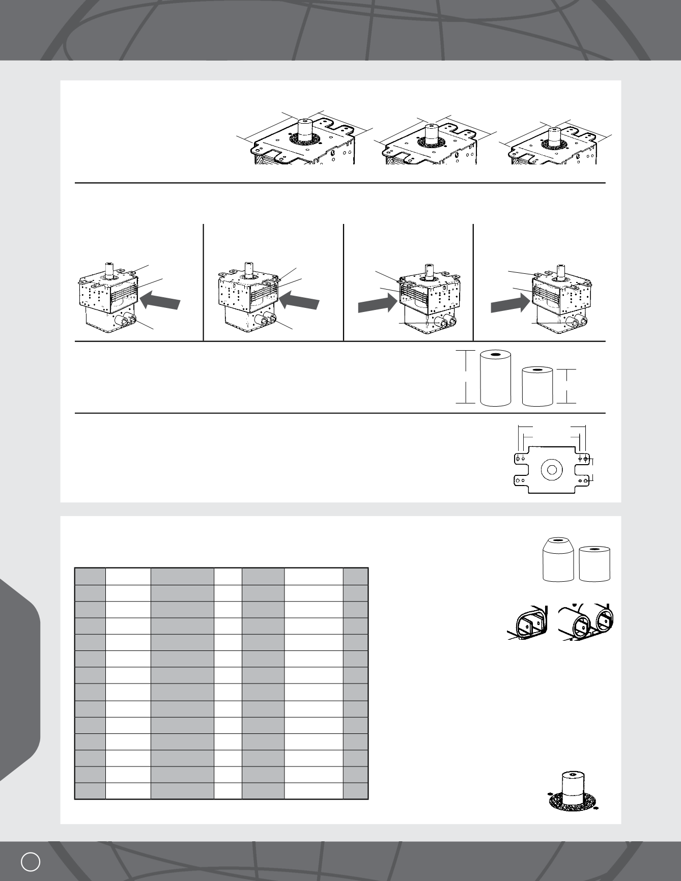
2) PHYSICAL CHARACTERISTICS
Match up size, configuration, antenna height & bracket
SIZE
Present-day magnetrons come in three
different sizes. In most cases, you cannot
replace a smaller one with a larger one due
to allotted space.
CONFIGURATION
Configuration is the relationship between the mounting ears, the vents (airflow) and the filament leads. Manufacturers have designated letter
codes for various configurations. The following are the four most popular configurations:
ANTENNA HEIGHT
Many manufacturers are enlarging the cavity size without increasing the overall size of the microwave.
They do this by reducing the size of the waveguide and shortening the antenna height.
BRACKET
The most popular bracket is what we refer to as the standard bracket. It has two sets of mounting ears coming off of
the opposite sides of the top plate of the magnetron with mounting holes spacing as shown. Some manufacturers
are using other style mounting brackets which cannot be replaced with our universal type brackets. See pages 24
through 30 for correct replacement.
E CONFIGURATION
Mounting ears opposite
vents and filament leads
STANDARD
COMPACT
SUBCOMPACT
H CONFIGURATION
Vents and mounting ears
in line with filament leads
J CONFIGURATION
Vent and mounting ears
opposite filament leads
K CONFIGURATION
Mounting ears and filament
leads opposite vents
95mm
80mm
80mm
80mm
73mm
70mm
Mounting Ears
Filament Leads
Vent
Air Flow
Mounting Ears
Filament Leads
Vent
Air Flow
Mounting Ears
Filament Leads
Vent
Air Flow
Mounting Ears
Filament Leads
Vent
Air Flow
114mm
95mm
35mm
30mm
20mm
3) IDENTIFY PART NUMBER
Match the correct magnetron using the chart below of the most popular
magnetrons with standard bracket.
IMPORTANT NOTES
1. The shape of the antenna cover or the
size of the hole in the cover does not
affect the operation of the magnetron.
2. There are two standard ways manufacturers connect the
filament leads.
Fig. 1 Both leads housed in
one insulating block
Fig. 2 Each lead housed in its
own insulating block
In 99% of the applications, the filament leads consist of single
wires with a 1/4" quick disconnect female terminal. Therefore,
both styles are interchangeable. One percent of the time a
plastic block is used, which houses both individual wires.
If your replacement magnetron doesn’t accept this block,
remove the block and connect individual wires to the proper
terminal, making certain terminals do not arc against the
cabinet cover.
CAUTION
When reinstalling a removed magnetron,
for whatever reason, make certain woven
metal RF gasket is properly seated at base
of antenna.
For magnetrons with special brackets and 20 mm antennas, see magnetron
section on pages 24 - 30.
Fig. 1
Fig. 2
4.35
900-1000
Standard E 30mm 10QBP1007 117
4.35
900-1000
Standard H 30mm 10QBP1003 117
4.35
900-1000
Standard J
30mm 10QBP1005 117
4.35
900-1000
Standard K 30mm 10QBP1004 118
4.1 700-850 Standard E 30mm 10QBP0235 118
4.1 700-850 Standard H 30mm 10QBP0231 118
4.1 700-850 Standard J
30mm 10QBP0230 118
4.1 700-850 Standard K 30mm 10QBP0232 119
4.1 700-850 Compact
E 30mm 10QBP0239 119
4.1 700-850 Compact
H 30mm 10QBP0226 119
4.1 700-850 Compact
J
30mm 10QBP0234 119
4.1 700-850 Compact
K 30mm 10QBP0228 120
3.8 500-650 Subcompact H 30mm 10QBP0311 120
3.8 500-650 Subcompact
J
30mm 10QBP0315 120
kV
Watts
Size
Config. Antenna
Part No.
Page


