
All logos, trademarks, part numbers, photos & illustrations are intended solely for identification.
Items offered for sale are not represented to be manufactured by the company that built the original equipment.
139
TRANSFORMERS
MICROWAVE
Order No. 16QBP0293
Installation instructions
(see wiring diagram on the next page)
1. Place transformer in position so that the label on top of the unit is
correctly oriented and readable.
2. The two terminals located on the lower windings are the primary
terminals for 120V line input.
3. The single terminal on the upper windings is the high voltage secondary
terminal and is connected to the low side of the capacitor.
4. The flying lead located at the front of the unit is connected to the high
side of the capacitor. The flying lead wire with the insulated terminal is
connected to the“FA”terminal of the magnetron.
Universal
4.1 kV output
(after doubling circuit)
700-850 watts, 3.3 volt, 300mA
Horizontal stack type
3" H x 4-1/8" W x 3-7/8" D
Order No. 16QBP0296
Installation instructions
(see wiring diagram on the next page)
1. Place transformer in position so that the label on top of the unit is
correctly oriented and readable.
2. The two terminals located on the lower windings are the primary
terminals for 120V line input.
3. The single red wire off the backside of the upper windings is the high
voltage secondary lead and is connected to the low side of the capacitor.
4. The two leads connected to the insulated terminal block are the filament
leads and are connected to the filament terminal coming off of the
magnetron. The single wire side is connected to the“FA”terminal. The
flying lead coming out of the dual filament terminal block is connected
to the high side of the capacitor (diode side).
Universal
4.35 kV output
(after doubling circuit)
900-1000 watts, 3.2 volt, 350mA
Horizontal stack type
3-7/8" W x 5-1/4" D x 3-1/2" H
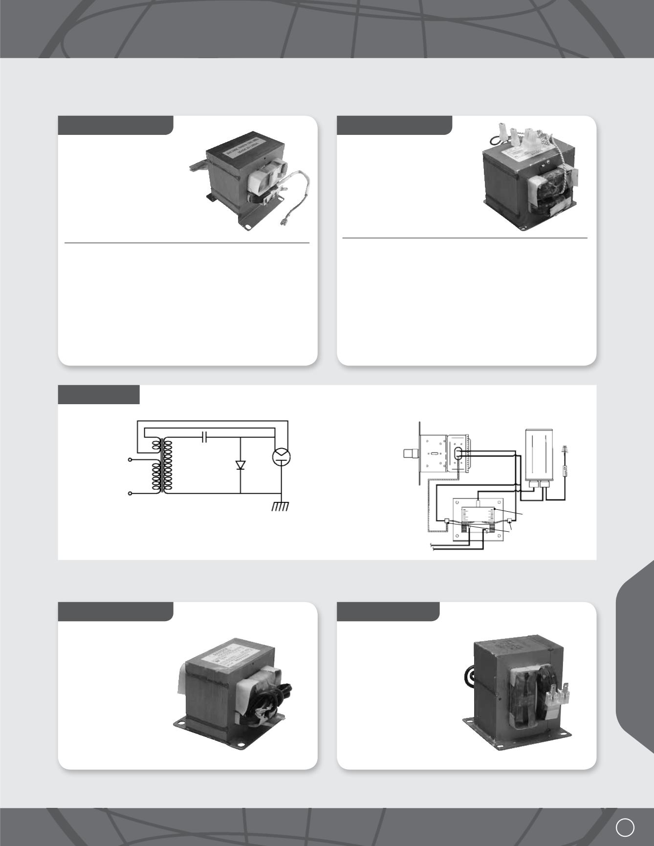
Wiring Instructions
Half-wave doubler L-C stabilized power
supply circuit for typical microwave oven
Wiring diagram for typical
microwave oven power supply
T1A Transformer primary
T1B Transformer HV windings
T1C Transformer filament
C1 Capacitor
D1 Diode
V1 Magnatron tube
LOW HIGH
T1C
T1A
T1B
C1
D1
F
FA
V1
Magnetron
Capacitor
HV
High
Low
Diode
To 120V source
Alternate
wiring method
Transformer
Filament
Order No. 16QBP4274
120 volt
Horizontal stack type
Replacement for Sharp
Order No. 16QBP4374
120 volt
Horizontal stack type
Replacement for Sharp
UNIVERSAL HV TRANSFORMERS
EXACT REPLACEMENT HV TRANSFORMERS


